
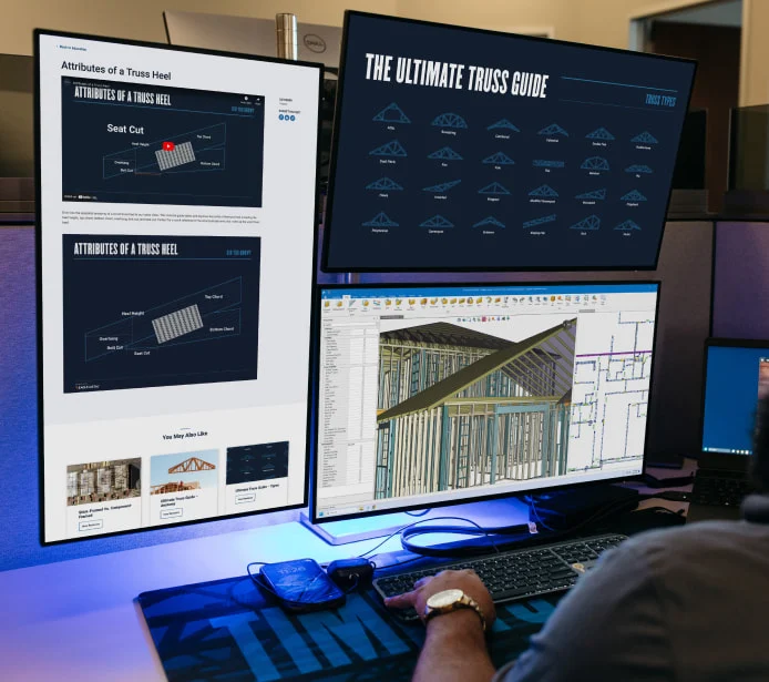

Ultimate Truss Guide – Anatomy
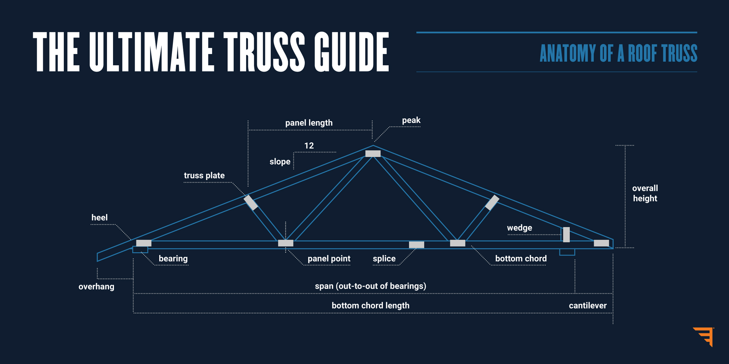
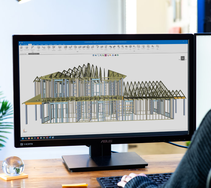
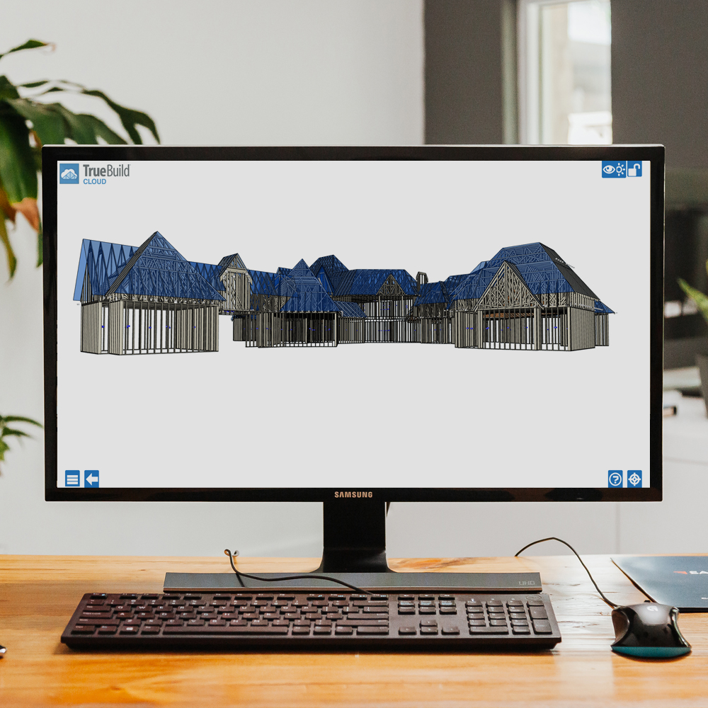
Dive into the intricacies of roof truss design with this truss anatomy illustration that breaks down the anatomy of a single roof truss, providing a detailed guide for component manufacturers to more easily communicate with customers when needed.
The bottom chord, a crucial truss component, carries combined tension and bending stresses, transferring forces to truss bearings. Traditionally cut from 2x lumber, it can vary in size and material. For stability, floor truss bottom chords are often oriented in a 4x2 configuration, while roof truss bottom chords are cut at angles to match the roof pitch, creating strong joints. Intersecting with top chords and web members, bottom chords are secured by metal connector plates and may be spliced with additional lumber for increased strength and load capacity.
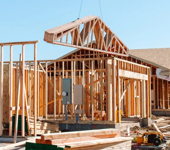
The cantilever extends beyond the truss support, allowing both chords to function beyond the bearings. Special webbing ensures load transfer. Cantilevers can comprise up to one-third of the truss span, often replacing traditional porch posts. This design minimizes costs and can substitute for overhangs, creating height within the truss.
A continuous lateral brace (CLR) reduces the unsupported length of truss members, preventing lateral deformation and buckling from imposed loads. CLRs stiffen web or chord members, often serving as an economical alternative to increasing member size or lumber grades. They're crucial in preventing truss failure by transferring extreme loads to adjacent trusses. However, CLRs may not always be feasible, necessitating alternatives like T-braces or L-braces. Truss installers must ensure proper bracing during and after installation, consulting Truss Design Drawings (TDD) and the BCSI for guidance.
The truss heel, where top and bottom chords intersect, typically rests over the outer bearing and varies based on design. In standard heel applications, it includes a minimum ¼” butt cut and height-measured plumb. Raised heels increase roof capacity for ventilation and insulation, with methods like sliders or reinforcing webs used to adjust the height. Architecturally significant, heel design impacts roof and structure interaction, yet may lack specification in construction documents, requiring scaling for accuracy.
The truss height, measured vertically from the bearing to the peak, varies based on span, pitch, heel, and truss type. It affects building design by determining overall height, which includes truss height, sheathing, wall heights, and floor containers. Different truss types, such as common or mono trusses, position the peak differently within the truss.
Overhangs extend beyond a structure's bearing, ranging from 6” to 36”. Longer overhangs may need additional support like a structural fascia board or beam. In pitched roof applications, overhangs follow the slope of the top chord and can affect header heights for windows and doors. Materials for overhangs usually match the top chord, though some truss technicians splice near the bearing for cost savings or architectural requirements. Visual appearance is crucial for exposed overhangs, with precautions taken during shipping to protect against damage.
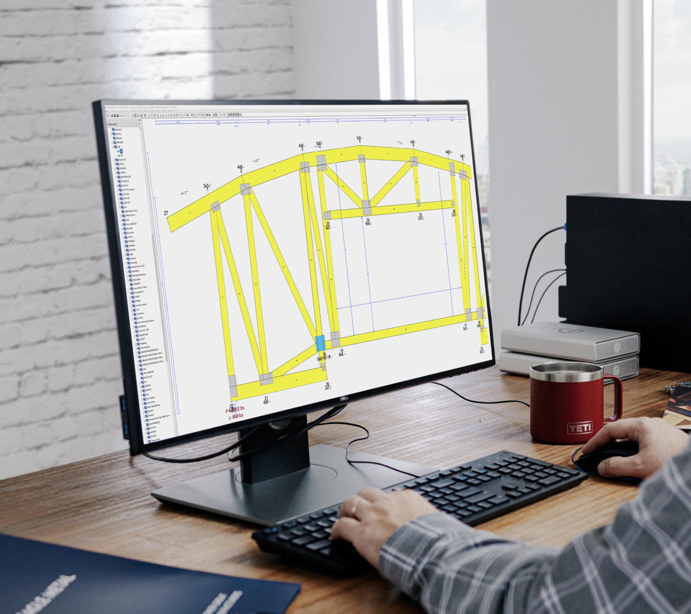
Panel Length refers to the horizontal distance between consecutive panel points along the top or bottom chord, crucial for determining material selection by the truss technician. These panels, defined by Panel Points, mark the intersections of web members and top or bottom chords, connected by metal connector plates. They play a vital role in the triangulation of the truss, facilitating the transfer of forces to the bearings. Adjusting panel points, even minimally, can significantly impact truss efficiency, particularly when subjected to point loads. Thus, careful consideration of panel length and placement is essential to ensure optimal truss performance and adherence to design requirements.
The juncture of sloping chords marks the truss summit, where their inclines meet. In standard roof trusses, the peak sits centrally along the span, aligning with a uniform pitch from each bearing. Deviations in heel heights or pitches result in an offset peak, absent in trusses like hip or flat top chord variants. Essential for determining rafter length, this apex-to-overhang dimension guides roofing metal cuts in various structures, especially those employing custom-length roofing sheets. Additionally, the heel-to-peak measurement serves as a quality check during truss production, ensuring alignment and accuracy for proper assembly.
Roof pitch, expressed as inches of rise over inches of run (e.g., 5/12 for 5 inches rise over 12 inches run), dictates truss geometry. Standardized to 12 inches, it simplifies communication, varying from 0/12 for flat trusses to 24/12 for steep pitches. The pitch affects top chord length and, combined with span and heel height, determines overall truss height. In vaulted or cathedral trusses, ceiling pitch is usually half the roof pitch, accommodating design needs efficiently. Adjustments for specific requirements, like increased ceiling pitch, involve considerations such as span, loading, and building codes. Increasing heel height aids in such designs, providing space for webs and load transfer.
Span, defining the horizontal distance between exterior bearings, is pivotal in truss design, delineating the structure's width. Extending from as minimal as 1 foot to over 100 feet, it encompasses diverse architectural requirements and necessitates specialized handling for spans exceeding 60 feet, termed "long span trusses." Understanding the span is vital for ordering or requesting trusses, aligning with the building's width in simpler structures or determined through dedicated software for more complex designs.
At the splice point, where two chord members merge into one, facilitated by a metal connector plate, lies a crucial junction in truss construction. This juncture may occur at a panel point or between them, depending on design specifics and manufacturing preferences. Splices enable the consolidation of shorter pieces into longer chord members, optimizing lumber usage. Chord dimensions can be adjusted at splice points to meet engineering or architectural needs. The splice's length is determined by factors like lumber availability, span, and cutting preferences. Manufacturers may splice from the center outward or vice versa, depending on efficiency considerations.
At the apex of a truss, the top chord is crucial, forming the framework for the roof alongside the bottom chord and webs. Crafted from 2x4 or 2x6 lumber, its size varies based on factors like spacing, loads, span, and pitch. Joined with bottom chords and web members via metal connector plates, the top chord may consist of multiple lumber pieces, spliced together at joints or mid-panels. Variations can occur at splice points, while in trusses with overhangs, the top chord extends past the bearing, typically cut with a plumb cut at the peak and overhang, and square cuts at splices. For floor trusses, the top chord is usually made from 2x3 or 2x4 material, sometimes 2x6, oriented for stability during installation.
Creating stable structures involves the technique of triangulation, where rigid triangles are formed by securely fastening objects at their joints. This engineering practice utilizes triangular shapes to impart stability to various structures. In constructions like roof and floor trusses, wooden triangles are employed to distribute compression and tension forces efficiently to the bearings. Triangles, being the most basic geometric shape resistant to changes in form when side lengths are fixed, provide substantial structural stability in design.
Truss plates, typically made of steel coated with zinc or zinc-aluminum alloy, facilitate the lateral transmission of loads in wooden structures. They enable dimensional lumber to be securely fastened together, leveraging the principles of triangulation to create stable trusses. These plates come in various sizes and shapes, often square or rectangular, with teeth punched during manufacturing to enhance grip when embedded in wood. Manufacturing methods vary among producers, employing either roller presses or hydraulic presses to embed the plates into wood while meeting stringent quality control standards. Despite their similar appearances, truss plates are highly engineered products, each with unique characteristics shaped by mechanical dies during manufacturing.
Truss webs are integral to the structural integrity of trusses, linking the top and bottom chords to create triangular patterns. Typically made of 2x3 to 2x12 dimensional lumber, webs bear axial forces that transfer to the truss bearings. In floor truss applications, 2x3 or 2x4 material is common, often cut with bevels for a snug fit at joints. Automated saws with precise angles and lengths are used to cut webs efficiently, minimizing waste. Continuous lateral restraints (CLRs) are sometimes required for webs in compression to prevent buckling, denoted on design drawings. Additionally, alternative reinforcements like scabs or stacked webs can be employed when field-applied restraints are not feasible.
A triangular piece, typically crafted from 2x dimensional lumber, serves as a wedge inserted between the top and bottom chords of a truss, especially useful in cantilever setups. Its primary function involves facilitating the plating of heel joints, effectively transferring forces from the chords to the bearings. Truss technicians often explore alternatives such as sliders and reinforcing webs for optimizing plating options at heel joints, a decision guided by engineering analysis.
You May Also Like
Stick-Framed Vs. Component-Framed
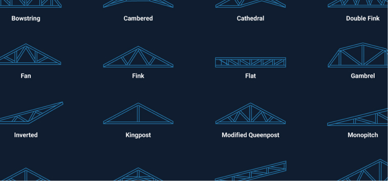
Ultimate Truss Guide – Types
Join our newsletter for news and updates on our software
Submit